Stirling It Up
Stirling engines are definitely a fairly niche topic. Since my initial knowledge about them was fairly limited, I had to do some research to figure out how exactly they work, and to learn about various ways of implementing them.
First of all, it is important to note where a Stirling engine draws its power from. Stirling engines are always situated between a heat source, and a heat sink. Heat naturally dissipates from the heat source to the heat sink, and a Stirling engine “steals” energy as it flows through the system, converting it into useful kinetic energy. In a fully closed system, the heat source and heat sink will eventually reach equilibrium, and the Stirling engine will then be unable to do any more work.
Stirling engines contain an internal fluid that transfers energy through the system. The fluid can expand, or contract, due to temperature changes — and as it does so, it drives one or more pistons within the engine, resulting in physical motion. If the system was this simple, however, it would soon reach an equilibrium and stop moving, as the piston would be pushed towards the heat sink by the expanding fluid on the side closest to the heat source, and energy would flow right through the piston to the heat sink. This is illustrated in the diagram below.

To fix this issue, Stirling engines contain a mechanism that displaces the fluid and “resets” the piston so that the fluid can expand and push it out once again. “Resetting” the piston in this way does require some energy, but if the engine is designed properly, there should still be a net positive amount of power produced by the engine. This is a very general explanation of how Stirling engines work, which should hopefully make more sense after going through the details.
There are two main types of Stirling engines — Alpha and Beta (there is also a Gamma type, which is a variation on Beta). Alpha type engines contain two cylinders, each with a piston — one cylinder is a heat source, and one is a heat sink. The fluid moves back and forth between the cylinders, and the pistons themselves act as the fluid displacers. Beta type engines contain one cylinder — with a heat source on one end and a heat sink on the other. The cylinder contains a piston, and a dedicated displacer which moves the fluid between the ends of the cylinder.
Beta type engines require a complex mechanical seal that allows a rod to be actuated through a piston head — this doesn’t seem feasible for me to construct. I’ve decided to develop an Alpha type engine instead, since the Alpha type seems mechanically simpler.
Alpha Engine Motion Explanation
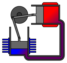
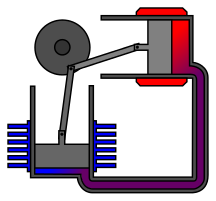
In the following diagrams, the red cylinder is the heat source, and the blue cylinder is the heat sink. Red fluid is heated and wants to expand; blue fluid is cooled and wants to contract. There is a conduit between the cylinders for the fluid to pass through. Each piston head is connected to a spinning flywheel, which stores momentum and keeps the engine moving, even when it is in a configuration that does not produce power.
Alpha Stirling engines operate in a continuous cycle through the following configurations, in the order illustrated.
Configuration 1:
In this configuration, the heat source piston has just extended to its maximum volume, while the heat sink piston is extending. The extension of the heat source cylinder has been powered by the expansion of fluid within that cylinder, due to an external heat source. The extension of the heat sink piston is being powered by momentum in the flywheel from the previous configuration (configuration 4), and by the extension of the heat source piston.
Configuration 2:
In this configuration, the system is powered by momentum from the flywheel. The heat source piston is forced to begin retracting, and the heat sink piston is forced to extend to its maximum volume. This increase in volume causes the temperature of the fluid to drop, all while it is forced into the heat sink cylinder.
Configuration 3:
In this configuration, the heat sink piston has started to retract, and the heat source cylinder has just retracted to its minimum volume. The retraction of the heat sink cylinder is being powered by the contraction of the fluid, due to the external environment absorbing energy from it. The retraction of the heat source piston is being powered by momentum in the flywheel from the previous configuration, and by the retraction of the heat sink piston.
Configuration 4:
In this configuration, the heat source piston is extending, and the heat sink piston has retracted to its minimum volume. The retraction of the heat sink piston has been powered by the contraction of fluid within it, as the external environment has absorbed energy from the fluid. Meanwhile, the extension of the heat sink piston is being powered by the expansion of the fluid within it, due to an external heat source. The fluid is compressed, and heats up, driving the engine into the next configuration.
The engine continues to power itself in this fashion. Useful energy can be extracted from the flywheel, as it spins, to do work. In practice, I doubt my engine will be able to do very much useful work after powering itself, though.
Regenerators
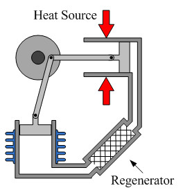
When the internal fluid is cooled, some energy will leave the system without ever doing any useful work, as it passes through the conduit. To mitigate this, many Stirling engines contain a regenerator (special material) within the conduit that absorbs heat energy, so that when the fluid is cooled, the fluid loses energy to the regenerator rather than to the external environment. When the fluid passes back through the regenerator at a later time, it can pick up some of this heat energy and do useful work in the heat source piston. I don’t think I will include a dedicated regenerator in my initial design due to the added complexity, but this may change in the future.
Sources Consulted
Keveney, M. “Animated Engines.” Animated Engines - Two Cylinder Stirling, animatedengines.com/vstirling.html.
NMRI - Types of Stirling Engines. www.nmri.go.jp/oldpages/eng/khirata/stirling/type/type00_e.html.
“Stirling Engine Regenerators – Explained.” Stirling Engines, www.stirlingengine.com/regenerators/.
First of all, it is important to note where a Stirling engine draws its power from. Stirling engines are always situated between a heat source, and a heat sink. Heat naturally dissipates from the heat source to the heat sink, and a Stirling engine “steals” energy as it flows through the system, converting it into useful kinetic energy. In a fully closed system, the heat source and heat sink will eventually reach equilibrium, and the Stirling engine will then be unable to do any more work.
Stirling engines contain an internal fluid that transfers energy through the system. The fluid can expand, or contract, due to temperature changes — and as it does so, it drives one or more pistons within the engine, resulting in physical motion. If the system was this simple, however, it would soon reach an equilibrium and stop moving, as the piston would be pushed towards the heat sink by the expanding fluid on the side closest to the heat source, and energy would flow right through the piston to the heat sink. This is illustrated in the diagram below.
To fix this issue, Stirling engines contain a mechanism that displaces the fluid and “resets” the piston so that the fluid can expand and push it out once again. “Resetting” the piston in this way does require some energy, but if the engine is designed properly, there should still be a net positive amount of power produced by the engine. This is a very general explanation of how Stirling engines work, which should hopefully make more sense after going through the details.
There are two main types of Stirling engines — Alpha and Beta (there is also a Gamma type, which is a variation on Beta). Alpha type engines contain two cylinders, each with a piston — one cylinder is a heat source, and one is a heat sink. The fluid moves back and forth between the cylinders, and the pistons themselves act as the fluid displacers. Beta type engines contain one cylinder — with a heat source on one end and a heat sink on the other. The cylinder contains a piston, and a dedicated displacer which moves the fluid between the ends of the cylinder.
Beta type engines require a complex mechanical seal that allows a rod to be actuated through a piston head — this doesn’t seem feasible for me to construct. I’ve decided to develop an Alpha type engine instead, since the Alpha type seems mechanically simpler.
Alpha Engine Motion Explanation
In the following diagrams, the red cylinder is the heat source, and the blue cylinder is the heat sink. Red fluid is heated and wants to expand; blue fluid is cooled and wants to contract. There is a conduit between the cylinders for the fluid to pass through. Each piston head is connected to a spinning flywheel, which stores momentum and keeps the engine moving, even when it is in a configuration that does not produce power.
Alpha Stirling engines operate in a continuous cycle through the following configurations, in the order illustrated.
Image from wikipedia.com
Configuration 1:
In this configuration, the heat source piston has just extended to its maximum volume, while the heat sink piston is extending. The extension of the heat source cylinder has been powered by the expansion of fluid within that cylinder, due to an external heat source. The extension of the heat sink piston is being powered by momentum in the flywheel from the previous configuration (configuration 4), and by the extension of the heat source piston.
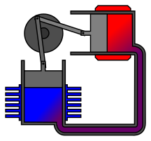
Image from wikipedia.com
Configuration 2:
In this configuration, the system is powered by momentum from the flywheel. The heat source piston is forced to begin retracting, and the heat sink piston is forced to extend to its maximum volume. This increase in volume causes the temperature of the fluid to drop, all while it is forced into the heat sink cylinder.
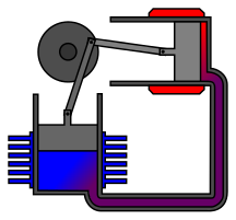
Image from wikipedia.com
Configuration 3:
In this configuration, the heat sink piston has started to retract, and the heat source cylinder has just retracted to its minimum volume. The retraction of the heat sink cylinder is being powered by the contraction of the fluid, due to the external environment absorbing energy from it. The retraction of the heat source piston is being powered by momentum in the flywheel from the previous configuration, and by the retraction of the heat sink piston.
Image from wikipedia.com
Configuration 4:
In this configuration, the heat source piston is extending, and the heat sink piston has retracted to its minimum volume. The retraction of the heat sink piston has been powered by the contraction of fluid within it, as the external environment has absorbed energy from the fluid. Meanwhile, the extension of the heat sink piston is being powered by the expansion of the fluid within it, due to an external heat source. The fluid is compressed, and heats up, driving the engine into the next configuration.
The engine continues to power itself in this fashion. Useful energy can be extracted from the flywheel, as it spins, to do work. In practice, I doubt my engine will be able to do very much useful work after powering itself, though.
Regenerators
When the internal fluid is cooled, some energy will leave the system without ever doing any useful work, as it passes through the conduit. To mitigate this, many Stirling engines contain a regenerator (special material) within the conduit that absorbs heat energy, so that when the fluid is cooled, the fluid loses energy to the regenerator rather than to the external environment. When the fluid passes back through the regenerator at a later time, it can pick up some of this heat energy and do useful work in the heat source piston. I don’t think I will include a dedicated regenerator in my initial design due to the added complexity, but this may change in the future.
Image from stirlingengine.com
Sources Consulted
Keveney, M. “Animated Engines.” Animated Engines - Two Cylinder Stirling, animatedengines.com/vstirling.html.
NMRI - Types of Stirling Engines. www.nmri.go.jp/oldpages/eng/khirata/stirling/type/type00_e.html.
“Stirling Engine Regenerators – Explained.” Stirling Engines, www.stirlingengine.com/regenerators/.