Piston Stroke Efficiency
The next three posts, including this one, will be quite mathematical in nature — they will analyze the theoretical behaviour of various systems within the engine, with each post building on top of the others. In the end, I will have a theoretical model of a Stirling engine — taking into account the force, pressure, and energy within the system. I will be able to use this information to influence my design choices. This particular post will focus on how force is transmitted through the piston and rod, and how it acts on the flywheel. When the piston extends or retracts, not all of the force exerted by it is applied in the direction of the rod’s motion — therefore, only the component acting in this direction can do useful work. Similarly, when the rod moves, not all of the force exerted by it is applied to the flywheel. The proportion of the force exerted by the piston head that is felt by the flywheel changes as the flywheel rotates and the piston moves. In order to create a true mathematical model of a Stirling engine, it is first necessary to determine the relationship between flywheel angle and this force transmission.
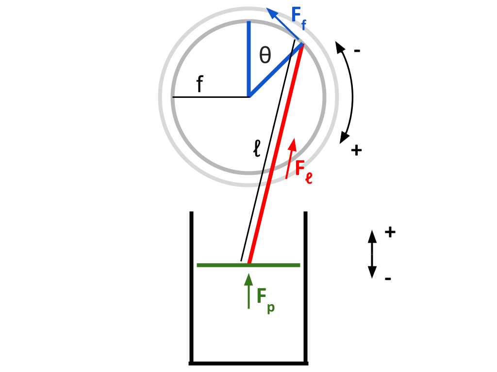
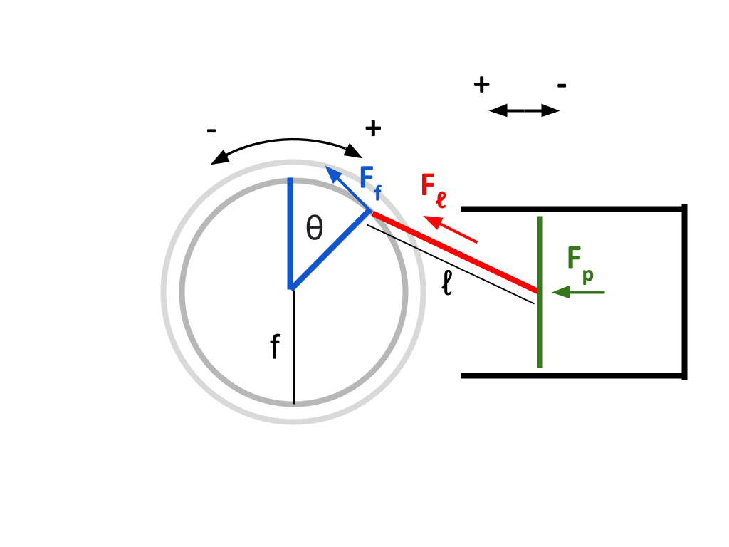
Both heat sink and heat source pistons will be mechanically identical, and so this derivation will only be shown for one piston — the other one is extremely similar. In a birds eye view, a piston and a flywheel are labelled:

The coordinate system given in the above diagram is used in the following derivations.
Let \(\theta\) represent the angle the flywheel has turned clockwise (as viewed in the diagram), with \(\theta = 0\) being the position where the piston rod is perpendicular to the piston head
Let \(ℓ\) represent the constant length of the piston rod (m)
Let \(f\) represent the constant radius from the center of the flywheel to the point of connection of the piston rod (m)
*note: I am purposely avoiding the letter r to avoid confusion with "radius"
Let \(F_p\) represent the force exerted on the piston head by the gas within the cylinder (N)
Let \(F_ℓ\) represent the force exerted on the piston rod along its direction of motion, by the piston head (N)
Let \(F_f\) represent the force exerted perpendicular to the flywheel’s radius by the piston rod (because this is the component that will cause the flywheel to turn) (N)
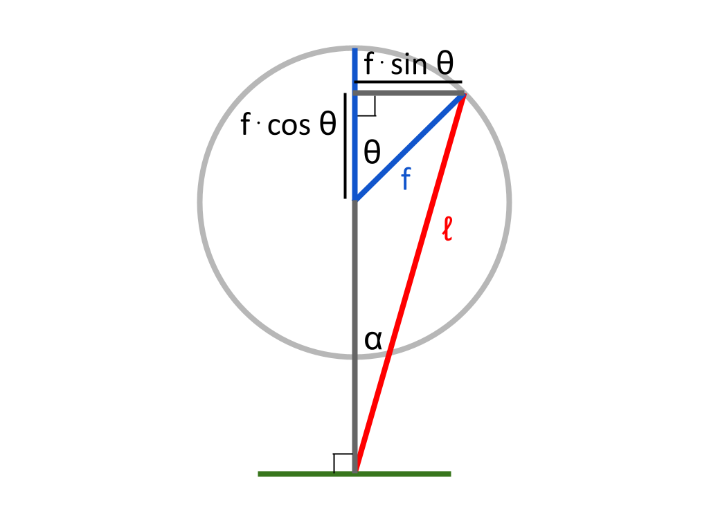
\(f · sin \theta\) and \(ℓ\) are two sides of a right triangle. The ratio \(sin \alpha\) in this triangle is given by \(f · sin \theta \over ℓ\). Therefore: $$\alpha = sin^{-1} {f · sin \theta \over ℓ}$$
If \(F_p\) is the force applied to the piston head, the component facing in the direction of \(ℓ\) will be \(F_ℓ\). Therefore: $$F_ℓ = F_p · cos \alpha$$
Looking back at the diagram from before:
We will now try to find the length \(d\) — the distance from the piston head to the center of the flywheel. This length is constantly changing as the flywheel rotates and the piston head moves.
\(d + f · cos \theta\) is one side of a right triangle, along with \(ℓ\) and \(f · sin \theta\). This means that \(d + f · cos \theta\) is \(\sqrt{ℓ^2 - (f · sin \theta)^2}\). So: $$d = \sqrt{ℓ^2 - (f · sin \theta)^2} - f · cos \theta$$
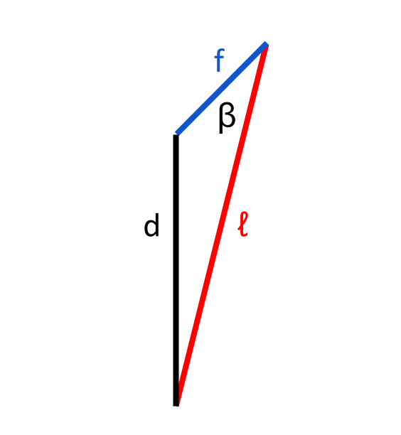
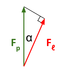
Taking a look at the diagram above, we can see that \(d\), \(ℓ\), and \(f\) form a triangle. This triangle contains the angle \(\beta\). Through the cosine law, we know that \(d^2 = ℓ^2 + f^2 - 2dℓ · cos \beta\). Rearranging this, we find that \(cos \beta = {ℓ^2 + f^2 - d^2 \over 2ℓf}\), and so: $$\beta = cos^{-1} {ℓ^2 + f^2 - d^2 \over 2ℓf}$$
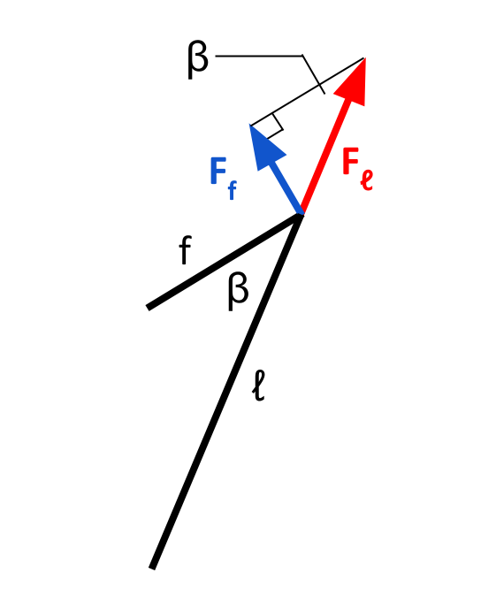
If the piston rod is pushed with a force of \(F_ℓ\), the component that will contribute to the flywheel’s motion is \(F_f\). Therefore, it seems that \(F_f = F_ℓ · sin \beta\). However, it is important to note that when \(\theta\) is between 0 and π, a positive force applied by the piston head will contribute to the flywheel’s motion in the negative direction. Likewise, when \(\theta\) is between π and 2π, a positive force applied by the piston head will contribute to the flywheel’s motion in the positive direction. To represent this relationship, we will need to multiply our expression for force by -1 over the interval \(0 ≤ \theta < \pi\), and by 1 over the interval \(\pi ≤ \theta < 2\pi\). Multiplying by \(-{|sin \theta| \over sin \theta}\) will achieve this effect. Therefore: $$F_f = -F_ℓ · sin \beta · {|sin \theta| \over sin \theta}$$
To summarize:
$$d = \sqrt{ℓ^2 - (f · sin \theta)^2} - f · cos \theta$$ $$\alpha = sin^{-1} {f · sin \theta \over ℓ}$$ $$\beta = cos^{-1} {ℓ^2 + f^2 - d^2 \over 2ℓf}$$ $$F_ℓ = F_p · cos \alpha$$ $$F_f = -F_ℓ · sin \beta · {|sin \theta| \over sin \theta}$$ Combining equations: $$F_f = -F_p · cos \alpha · sin \beta · {|sin \theta| \over sin \theta}$$
We do not yet have a value for \(F_p\) or \(F_f\), so this equation cannot be solved. However, we can solve for the ratio \(Fp \over Ff\) to find the proportion of the force applied by the piston that is felt by the flywheel. Since the only variable in these equations is \(\theta\) (the rest are constants), we can plot this proportion as a function of \(\theta\). This gives us a relationship between flywheel angle, and the proportion of useful force felt by the flywheel.
Doing so, we find the following graph:
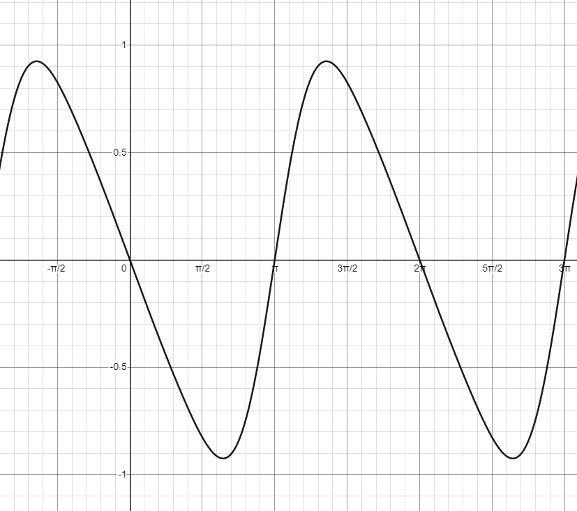
This looks pretty cool! It also appears to model force transmission correctly — we can do a quick mental check to see that at \(\theta = 0\) and \(\theta = {\pi \over 2}\), the piston rod cannot apply any useful force to the flywheel (this makes sense because at these points, the rod is collinear with the flywheel’s radius — and so it cannot apply any force perpendicular to the circle’s radius). Force transmission should also be negative from \(0 ≤ \theta < \pi\), and positive from \(\pi ≤ \theta < 2\pi\) — again, this checks out.
Using a similar process, we can find the equations that describe force transmission for the second piston. The angle \(\theta\) is shifted by \(\pi \over 2\) from the perspective of this piston. I won’t go through every step of the derivation here, since the process is so similar to the derivation for the first piston. Rather, this proof is left as an exercise to the reader ;)
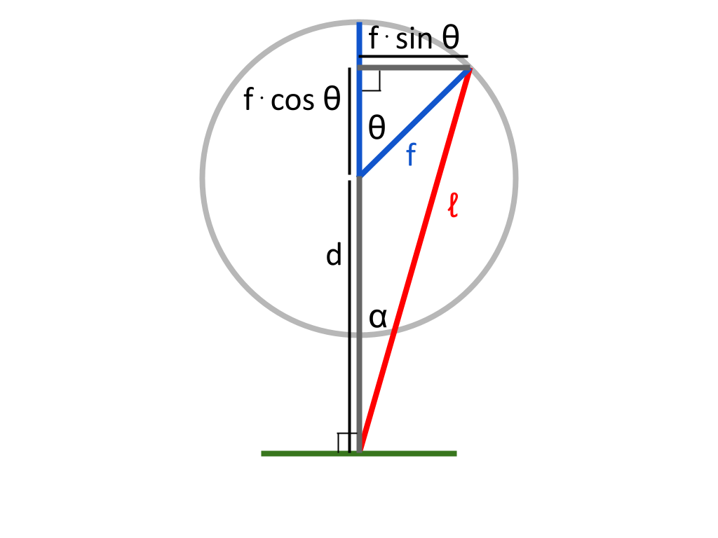
For the second piston, redefining all variables to refer to the above diagram:
$$d = \sqrt{ℓ^2 - (f · cos \theta)^2} + f · sin \theta$$ $$\alpha = sin^{-1} {f · cos \theta \over ℓ}$$ $$\beta = cos^{-1} {ℓ^2 + f^2 - d^2 \over 2ℓf}$$ $$F_ℓ = F_p · cos \alpha$$ $$F_f = -F_ℓ · sin \beta · {|cos \theta| \over cos \theta}$$ Combining equations: $$F_f = -F_p · cos \alpha · sin \beta · {|cos \theta| \over cos \theta}$$
Don’t worry, I’ll redefine unique variable names in future posts to refer to each individual piston so the variable names aren’t shared like this — since we’re only focusing on one piston at a time in this post, I didn’t feel it was necessary to be so specific.
Plotting both force transmission ratios with respect to flywheel angle:
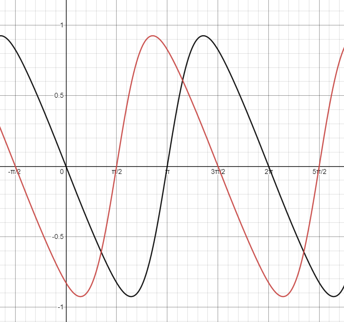
Once again, not only does it look pretty neat, it also checks out theoretically!
This Desmos graph used to plot these values can be found here: https://www.desmos.com/calculator/x5hilqnphk
More equations describing other systems in the engine will be added to this graph in future posts. In the next post, we will look at pressure in the engine as a function of \(\theta\).
Both heat sink and heat source pistons will be mechanically identical, and so this derivation will only be shown for one piston — the other one is extremely similar. In a birds eye view, a piston and a flywheel are labelled:
The coordinate system given in the above diagram is used in the following derivations.
Let \(\theta\) represent the angle the flywheel has turned clockwise (as viewed in the diagram), with \(\theta = 0\) being the position where the piston rod is perpendicular to the piston head
Let \(ℓ\) represent the constant length of the piston rod (m)
Let \(f\) represent the constant radius from the center of the flywheel to the point of connection of the piston rod (m)
*note: I am purposely avoiding the letter r to avoid confusion with "radius"
Let \(F_p\) represent the force exerted on the piston head by the gas within the cylinder (N)
Let \(F_ℓ\) represent the force exerted on the piston rod along its direction of motion, by the piston head (N)
Let \(F_f\) represent the force exerted perpendicular to the flywheel’s radius by the piston rod (because this is the component that will cause the flywheel to turn) (N)
\(f · sin \theta\) and \(ℓ\) are two sides of a right triangle. The ratio \(sin \alpha\) in this triangle is given by \(f · sin \theta \over ℓ\). Therefore: $$\alpha = sin^{-1} {f · sin \theta \over ℓ}$$
If \(F_p\) is the force applied to the piston head, the component facing in the direction of \(ℓ\) will be \(F_ℓ\). Therefore: $$F_ℓ = F_p · cos \alpha$$
Looking back at the diagram from before:
We will now try to find the length \(d\) — the distance from the piston head to the center of the flywheel. This length is constantly changing as the flywheel rotates and the piston head moves.
\(d + f · cos \theta\) is one side of a right triangle, along with \(ℓ\) and \(f · sin \theta\). This means that \(d + f · cos \theta\) is \(\sqrt{ℓ^2 - (f · sin \theta)^2}\). So: $$d = \sqrt{ℓ^2 - (f · sin \theta)^2} - f · cos \theta$$
Taking a look at the diagram above, we can see that \(d\), \(ℓ\), and \(f\) form a triangle. This triangle contains the angle \(\beta\). Through the cosine law, we know that \(d^2 = ℓ^2 + f^2 - 2dℓ · cos \beta\). Rearranging this, we find that \(cos \beta = {ℓ^2 + f^2 - d^2 \over 2ℓf}\), and so: $$\beta = cos^{-1} {ℓ^2 + f^2 - d^2 \over 2ℓf}$$
If the piston rod is pushed with a force of \(F_ℓ\), the component that will contribute to the flywheel’s motion is \(F_f\). Therefore, it seems that \(F_f = F_ℓ · sin \beta\). However, it is important to note that when \(\theta\) is between 0 and π, a positive force applied by the piston head will contribute to the flywheel’s motion in the negative direction. Likewise, when \(\theta\) is between π and 2π, a positive force applied by the piston head will contribute to the flywheel’s motion in the positive direction. To represent this relationship, we will need to multiply our expression for force by -1 over the interval \(0 ≤ \theta < \pi\), and by 1 over the interval \(\pi ≤ \theta < 2\pi\). Multiplying by \(-{|sin \theta| \over sin \theta}\) will achieve this effect. Therefore: $$F_f = -F_ℓ · sin \beta · {|sin \theta| \over sin \theta}$$
To summarize:
$$d = \sqrt{ℓ^2 - (f · sin \theta)^2} - f · cos \theta$$ $$\alpha = sin^{-1} {f · sin \theta \over ℓ}$$ $$\beta = cos^{-1} {ℓ^2 + f^2 - d^2 \over 2ℓf}$$ $$F_ℓ = F_p · cos \alpha$$ $$F_f = -F_ℓ · sin \beta · {|sin \theta| \over sin \theta}$$ Combining equations: $$F_f = -F_p · cos \alpha · sin \beta · {|sin \theta| \over sin \theta}$$
We do not yet have a value for \(F_p\) or \(F_f\), so this equation cannot be solved. However, we can solve for the ratio \(Fp \over Ff\) to find the proportion of the force applied by the piston that is felt by the flywheel. Since the only variable in these equations is \(\theta\) (the rest are constants), we can plot this proportion as a function of \(\theta\). This gives us a relationship between flywheel angle, and the proportion of useful force felt by the flywheel.
Doing so, we find the following graph:
This looks pretty cool! It also appears to model force transmission correctly — we can do a quick mental check to see that at \(\theta = 0\) and \(\theta = {\pi \over 2}\), the piston rod cannot apply any useful force to the flywheel (this makes sense because at these points, the rod is collinear with the flywheel’s radius — and so it cannot apply any force perpendicular to the circle’s radius). Force transmission should also be negative from \(0 ≤ \theta < \pi\), and positive from \(\pi ≤ \theta < 2\pi\) — again, this checks out.
Using a similar process, we can find the equations that describe force transmission for the second piston. The angle \(\theta\) is shifted by \(\pi \over 2\) from the perspective of this piston. I won’t go through every step of the derivation here, since the process is so similar to the derivation for the first piston. Rather, this proof is left as an exercise to the reader ;)
For the second piston, redefining all variables to refer to the above diagram:
$$d = \sqrt{ℓ^2 - (f · cos \theta)^2} + f · sin \theta$$ $$\alpha = sin^{-1} {f · cos \theta \over ℓ}$$ $$\beta = cos^{-1} {ℓ^2 + f^2 - d^2 \over 2ℓf}$$ $$F_ℓ = F_p · cos \alpha$$ $$F_f = -F_ℓ · sin \beta · {|cos \theta| \over cos \theta}$$ Combining equations: $$F_f = -F_p · cos \alpha · sin \beta · {|cos \theta| \over cos \theta}$$
Don’t worry, I’ll redefine unique variable names in future posts to refer to each individual piston so the variable names aren’t shared like this — since we’re only focusing on one piston at a time in this post, I didn’t feel it was necessary to be so specific.
Plotting both force transmission ratios with respect to flywheel angle:
Once again, not only does it look pretty neat, it also checks out theoretically!
This Desmos graph used to plot these values can be found here: https://www.desmos.com/calculator/x5hilqnphk
More equations describing other systems in the engine will be added to this graph in future posts. In the next post, we will look at pressure in the engine as a function of \(\theta\).