Under Pressure
In this post, we will look at pressure in the Stirling engine as a function of \(\theta\), and use that to determine the forces experienced by the flywheel as a function of \(\theta\). We will need to consider the system as a whole when doing this.
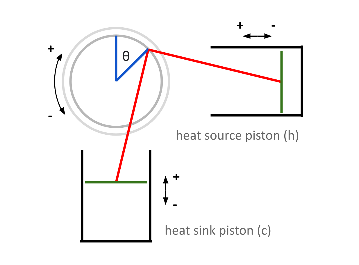
Although the two pistons are mechanically identical, they have unique temperatures, and unique volumes with respect to \(\theta\) — information that will be important when considering the system’s overall pressure. As such, we will need a new convention to differentiate between each piston. Recall that in the last post, we focused on each piston individually, so this wasn’t really necessary. From now on, any variable with a subscript \(c\) will refer to a property of the heat sink (think “cold”) piston, and any variable with a subscript \(h\) will refer to a property of the heat source (think “hot”) piston.

First, we will take a look at the internal volume of each piston with respect to \(\theta\). We will need to use the quantity \(d\) from the last post — remember that \(d\) represents the length from the moving piston head to the center of the flywheel.
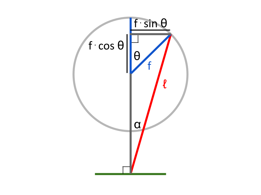
Each piston will have a different, varying length \(d\) with respect to \(\theta\). As derived in the previous post: $$d_c = \sqrt{ℓ^2 - (f · sin \theta)^2} - f · cos \theta$$ $$d_h = \sqrt{ℓ^2 - (f · cos \theta)^2} + f · sin \theta$$
We will also need to define some new values.
Let \(c\) represent the constant internal radius of the cylinders (m)
Let \(h\) represent the constant maximum internal length of each cylinder, from its base to the piston head when the piston is fully extended (m)
(Since both pistons are mechanically identical, we can use the same constants, \(c\) and \(h\), for both)
Let \(V_c\) represent the internal volume of the heat sink cylinder (m3)
Let \(V_h\) represent the internal volume of the heat source cylinder (m3)
As a next step in finding an expression for each cylinder’s volume with respect to \(\theta\), we will find an expression for the internal length of each cylinder with respect to \(\theta\).
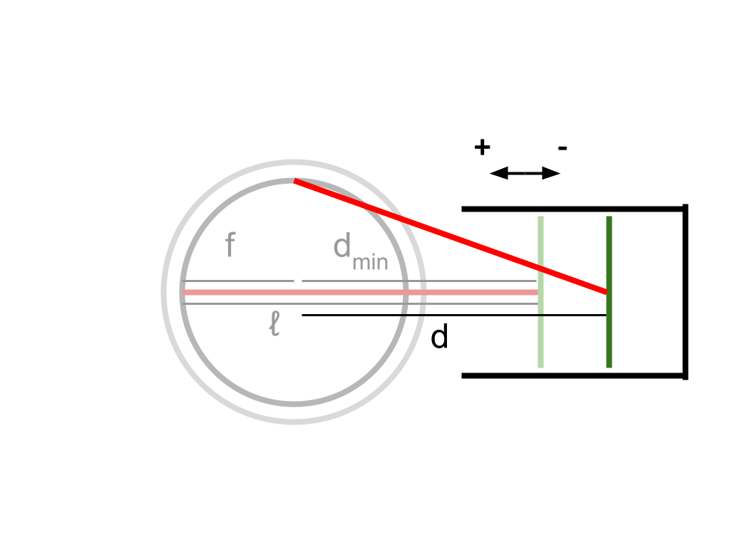
Since \(h\) is the maximum length of the cylinder when the piston is fully extended, we can subtract from \(h\) the length that the piston has contracted (from its maximum extension) at any point in time to find the current length of the cylinder.
From the diagram, it can be seen that when the piston is fully extended, \(ℓ - f\) is a constant which is equivalent to \(d\) — specifically, at this point, the smallest possible value of \(d\). If at any point we subtract the current value of \(d\) from \(ℓ - f\), we will find the difference between the smallest possible value of \(d\), and the current value of \(d\) — which represents the length that the piston head has retracted from its fully extended position. This subtraction gives us the length of the current piston contraction as a negative result, which we can add to \(h\) to find the current length of the cylinder. To summarize, the internal length of the cylinder with respect to \(\theta\) is \(h + ℓ - f - d\).
To find the cylinder’s volume, we will multiply the internal area of its base by its height. Since the internal radius of the base is \(c\), its internal area is \(\pi c^2\). Therefore: $$V_c = \pi c^2 · (h + ℓ - f - d_c)$$ $$V_h = \pi c^2 · (h + ℓ - f - d_h)$$
Now, we have an expression for the volume of each cylinder with respect to \(\theta\) (keeping in mind that \(d\) is ultimately a value that changes with respect to \(\theta\)). To determine the pressure within the system, we will need to head to the magical land on the border of chemistry and physics, and take a look at the general form of the ideal gas law.
$$PV = nRT$$
This equation relates pressure and volume in a system to the quantity of gas molecules the system contains, as well as the temperature within the system. In a Stirling engine, each cylinder contains gas at a different temperature, and at any point in time, each cylinder has a different volume and contains a different amount of gas. However, we will assume that pressure is always constant throughout every part of the engine — even between cylinders. This will vastly simplify our calculations. Technically, this isn’t entirely true, but pressure variations do spread quite rapidly, and in practice this is probably a fair assumption. We can define the variables in the ideal gas law in the context of this engine.
Let \(T_c\) represent the constant internal temperature of the heat sink cylinder (K)
Let \(T_h\) represent the constant internal temperature of the heat source cylinder (K)
Let \(n_c\) represent the quantity of air molecules within the heat sink cylinder (mol)
Let \(n_h\) represent the quantity of air molecules within the heat source cylinder (mol)
Let \(n\) represent the quantity of air molecules within the engine as a whole (mol)
Let \(P\) represent the pressure within the engine as a whole (Pa)
We will also define some environmental constants and their values:
Let \(R\) represent the Boltzmann constant in SI units (J/K)
Let \(T_a\) represent the constant ambient temperature (K)
Let \(P_a\) represent the constant ambient atmospheric pressure (Pa)
\(R = 8.3145 \space {J \over mol·K}\)
\(T_a = 293 \space K\)
\(P_a = 101,325 \space Pa\)
The quantity of air molecules within the engine, represented by \(n\), should always remain constant since the system is sealed. If we find the amount of air that is initially contained in the engine, this amount will not change as the engine operates. Without any sort of external pump, it is possible to initially seal in anywhere between 1 and 2 full cylinders of air within the system. I will assume that I can fit 1.75 cylinders worth of air within the engine —to do this, I will need to initially compress some air by hand. This will be done at the standard environmental conditions defined above. The ideal gas law can be used to find out how much air the system will initially contain when this is done.
Keeping in mind that the volume of 1.75 cylinders can be expressed as \(1.75 \pi c^2 h \space m^3\):
$$PV = nRT$$
$$n = PV/RT$$
$$n = {P_a · (1.75πc^2h \space m^3) \over RT_a}$$
\(n\) is a constant value that does not change with respect to \(\theta\). This is the total amount of air in the system, at any given time.
Similarly, we can express the quantity of air that each individual cylinder contains — keeping in mind that each has a different temperature, and that each cylinder’s volume continually changes with respect to \(\theta\). We know that in general, \(n = {PV \over RT}\), so: $$n_c = {PV_c \over RT_c}$$ $$n_h = {PV_h \over RT_h}$$
We also know that at any point in time, the sum of the quantity of air in both cylinders equals the total amount of air within the engine. Mathematically:
$$n = n_c + n_h$$
Therefore, it is always true that:
$$n = {PV_c \over RT_c} + {PV_h \over RT_h}$$
In this equation, the internal pressure is the same throughout the engine, and the temperature within each cylinder is constant, but the volume of each cylinder is constantly changing with respect to \(\theta\).
We can rearrange this equation to solve for the internal pressure of the engine: $$P = {nRT_cT_h \over V_cT_h + V_hT_c}$$
Each piston will indeed experience this internal pressure, but in reality, this internal pressure value is slightly misleading, because each piston will also experience an external atmospheric pressure — \(P_a\). Since these pressures will result in forces on the piston in opposite directions, the relative pressure within the piston is actually lower than this absolute, internal pressure.
Let \(P_r\) represent the relative pressure within the engine (Pa)
To find the relative pressure within the piston, we simply need to find the pressure difference across its interior and exterior (the internal pressure is positive in this equation, since it pushes outwards in the positive direction): $$P_r = P - P_a$$
This expression gives relative pressure as a function of \(\theta\). In order to plot this relationship, I have chosen some arbitrary, but reasonable values for the constants \(ℓ\), \(f\), \(c\), and \(h\) since they haven’t yet been defined. The exact values aren’t relevant at this stage, but this graph’s shape gives a general idea of how pressure varies in the system as a function of \(\theta\).
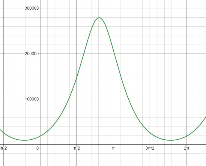
Once again, another neat looking function! It also seems to check out — the highest pressure in a cycle is within the interval \({\pi \over 2} < \theta < \pi\), where the combined volume of the cylinders is at its lowest. Conversely, the lowest pressure in a cycle is within the interval \({3 \pi \over 2} < \theta < 2 \pi\), where the combined volume of the cylinders is at its highest.
Now that we know the relative pressure within the engine at any flywheel angle, we can relate this to the force felt by the piston heads — this quantity is \(F_p\) from the last post. Pressure is, by definition, a measure of force distributed over a certain area — and so, multiplying the relative pressure within the piston by the area of the piston head gives the net force felt by the piston head as a result of internal and external pressure. The area of the piston head is simply \(\pi c^2\), and so: $$F_p = P_r · \pi c^2$$
Since both pistons are mechanically identical, and because the pressure within the engine is consistent between cylinders, both piston heads experience the same force \(F_p\) at every point in time. However, as we explored in the last post, at every flywheel angle a different amount of force is transferred from each piston head to the flywheel.
Let \(F_c\) represent the component of the force applied by the heat sink piston head that contributes to the flywheel’s motion (N)
Let \(F_h\) represent the component of the force applied by the heat source piston head that contributes to the flywheel’s motion (N)
Based on the force transmission equations from the previous post: $$F_c = -F_p · cos \alpha_c · sin \beta_c · {|sin \theta| \over sin \theta}$$ $$F_h = -F_p · cos \alpha_h · sin \beta_h · {|cos \theta| \over cos \theta}$$
Using the same arbitrary constants from before, we can plot these forces with respect to \(\theta\).

This yields another pretty graph! The purple curve represents \(F_c\), and the orange curve represents \(F_h\). Note that although these curves appear to be vertically symmetrical, ignoring the phase shift, they actually aren’t — in general, the flywheel actually appears to experience greater positive forces than negative ones.
We will investigate this further in the next post, when we take a look at how these forces impart energy to the flywheel.
The Desmos graph used in this post can be found here: https://www.desmos.com/calculator/bsfyk3k1nn
Although the two pistons are mechanically identical, they have unique temperatures, and unique volumes with respect to \(\theta\) — information that will be important when considering the system’s overall pressure. As such, we will need a new convention to differentiate between each piston. Recall that in the last post, we focused on each piston individually, so this wasn’t really necessary. From now on, any variable with a subscript \(c\) will refer to a property of the heat sink (think “cold”) piston, and any variable with a subscript \(h\) will refer to a property of the heat source (think “hot”) piston.
First, we will take a look at the internal volume of each piston with respect to \(\theta\). We will need to use the quantity \(d\) from the last post — remember that \(d\) represents the length from the moving piston head to the center of the flywheel.
Each piston will have a different, varying length \(d\) with respect to \(\theta\). As derived in the previous post: $$d_c = \sqrt{ℓ^2 - (f · sin \theta)^2} - f · cos \theta$$ $$d_h = \sqrt{ℓ^2 - (f · cos \theta)^2} + f · sin \theta$$
We will also need to define some new values.
Let \(c\) represent the constant internal radius of the cylinders (m)
Let \(h\) represent the constant maximum internal length of each cylinder, from its base to the piston head when the piston is fully extended (m)
(Since both pistons are mechanically identical, we can use the same constants, \(c\) and \(h\), for both)
Let \(V_c\) represent the internal volume of the heat sink cylinder (m3)
Let \(V_h\) represent the internal volume of the heat source cylinder (m3)
As a next step in finding an expression for each cylinder’s volume with respect to \(\theta\), we will find an expression for the internal length of each cylinder with respect to \(\theta\).
Since \(h\) is the maximum length of the cylinder when the piston is fully extended, we can subtract from \(h\) the length that the piston has contracted (from its maximum extension) at any point in time to find the current length of the cylinder.
From the diagram, it can be seen that when the piston is fully extended, \(ℓ - f\) is a constant which is equivalent to \(d\) — specifically, at this point, the smallest possible value of \(d\). If at any point we subtract the current value of \(d\) from \(ℓ - f\), we will find the difference between the smallest possible value of \(d\), and the current value of \(d\) — which represents the length that the piston head has retracted from its fully extended position. This subtraction gives us the length of the current piston contraction as a negative result, which we can add to \(h\) to find the current length of the cylinder. To summarize, the internal length of the cylinder with respect to \(\theta\) is \(h + ℓ - f - d\).
To find the cylinder’s volume, we will multiply the internal area of its base by its height. Since the internal radius of the base is \(c\), its internal area is \(\pi c^2\). Therefore: $$V_c = \pi c^2 · (h + ℓ - f - d_c)$$ $$V_h = \pi c^2 · (h + ℓ - f - d_h)$$
Now, we have an expression for the volume of each cylinder with respect to \(\theta\) (keeping in mind that \(d\) is ultimately a value that changes with respect to \(\theta\)). To determine the pressure within the system, we will need to head to the magical land on the border of chemistry and physics, and take a look at the general form of the ideal gas law.
$$PV = nRT$$
This equation relates pressure and volume in a system to the quantity of gas molecules the system contains, as well as the temperature within the system. In a Stirling engine, each cylinder contains gas at a different temperature, and at any point in time, each cylinder has a different volume and contains a different amount of gas. However, we will assume that pressure is always constant throughout every part of the engine — even between cylinders. This will vastly simplify our calculations. Technically, this isn’t entirely true, but pressure variations do spread quite rapidly, and in practice this is probably a fair assumption. We can define the variables in the ideal gas law in the context of this engine.
Let \(T_c\) represent the constant internal temperature of the heat sink cylinder (K)
Let \(T_h\) represent the constant internal temperature of the heat source cylinder (K)
Let \(n_c\) represent the quantity of air molecules within the heat sink cylinder (mol)
Let \(n_h\) represent the quantity of air molecules within the heat source cylinder (mol)
Let \(n\) represent the quantity of air molecules within the engine as a whole (mol)
Let \(P\) represent the pressure within the engine as a whole (Pa)
We will also define some environmental constants and their values:
Let \(R\) represent the Boltzmann constant in SI units (J/K)
Let \(T_a\) represent the constant ambient temperature (K)
Let \(P_a\) represent the constant ambient atmospheric pressure (Pa)
\(R = 8.3145 \space {J \over mol·K}\)
\(T_a = 293 \space K\)
\(P_a = 101,325 \space Pa\)
The quantity of air molecules within the engine, represented by \(n\), should always remain constant since the system is sealed. If we find the amount of air that is initially contained in the engine, this amount will not change as the engine operates. Without any sort of external pump, it is possible to initially seal in anywhere between 1 and 2 full cylinders of air within the system. I will assume that I can fit 1.75 cylinders worth of air within the engine —to do this, I will need to initially compress some air by hand. This will be done at the standard environmental conditions defined above. The ideal gas law can be used to find out how much air the system will initially contain when this is done.
Keeping in mind that the volume of 1.75 cylinders can be expressed as \(1.75 \pi c^2 h \space m^3\):
$$PV = nRT$$
$$n = PV/RT$$
$$n = {P_a · (1.75πc^2h \space m^3) \over RT_a}$$
\(n\) is a constant value that does not change with respect to \(\theta\). This is the total amount of air in the system, at any given time.
Similarly, we can express the quantity of air that each individual cylinder contains — keeping in mind that each has a different temperature, and that each cylinder’s volume continually changes with respect to \(\theta\). We know that in general, \(n = {PV \over RT}\), so: $$n_c = {PV_c \over RT_c}$$ $$n_h = {PV_h \over RT_h}$$
We also know that at any point in time, the sum of the quantity of air in both cylinders equals the total amount of air within the engine. Mathematically:
$$n = n_c + n_h$$
Therefore, it is always true that:
$$n = {PV_c \over RT_c} + {PV_h \over RT_h}$$
In this equation, the internal pressure is the same throughout the engine, and the temperature within each cylinder is constant, but the volume of each cylinder is constantly changing with respect to \(\theta\).
We can rearrange this equation to solve for the internal pressure of the engine: $$P = {nRT_cT_h \over V_cT_h + V_hT_c}$$
Each piston will indeed experience this internal pressure, but in reality, this internal pressure value is slightly misleading, because each piston will also experience an external atmospheric pressure — \(P_a\). Since these pressures will result in forces on the piston in opposite directions, the relative pressure within the piston is actually lower than this absolute, internal pressure.
Let \(P_r\) represent the relative pressure within the engine (Pa)
To find the relative pressure within the piston, we simply need to find the pressure difference across its interior and exterior (the internal pressure is positive in this equation, since it pushes outwards in the positive direction): $$P_r = P - P_a$$
This expression gives relative pressure as a function of \(\theta\). In order to plot this relationship, I have chosen some arbitrary, but reasonable values for the constants \(ℓ\), \(f\), \(c\), and \(h\) since they haven’t yet been defined. The exact values aren’t relevant at this stage, but this graph’s shape gives a general idea of how pressure varies in the system as a function of \(\theta\).
Once again, another neat looking function! It also seems to check out — the highest pressure in a cycle is within the interval \({\pi \over 2} < \theta < \pi\), where the combined volume of the cylinders is at its lowest. Conversely, the lowest pressure in a cycle is within the interval \({3 \pi \over 2} < \theta < 2 \pi\), where the combined volume of the cylinders is at its highest.
Now that we know the relative pressure within the engine at any flywheel angle, we can relate this to the force felt by the piston heads — this quantity is \(F_p\) from the last post. Pressure is, by definition, a measure of force distributed over a certain area — and so, multiplying the relative pressure within the piston by the area of the piston head gives the net force felt by the piston head as a result of internal and external pressure. The area of the piston head is simply \(\pi c^2\), and so: $$F_p = P_r · \pi c^2$$
Since both pistons are mechanically identical, and because the pressure within the engine is consistent between cylinders, both piston heads experience the same force \(F_p\) at every point in time. However, as we explored in the last post, at every flywheel angle a different amount of force is transferred from each piston head to the flywheel.
Let \(F_c\) represent the component of the force applied by the heat sink piston head that contributes to the flywheel’s motion (N)
Let \(F_h\) represent the component of the force applied by the heat source piston head that contributes to the flywheel’s motion (N)
Based on the force transmission equations from the previous post: $$F_c = -F_p · cos \alpha_c · sin \beta_c · {|sin \theta| \over sin \theta}$$ $$F_h = -F_p · cos \alpha_h · sin \beta_h · {|cos \theta| \over cos \theta}$$
Using the same arbitrary constants from before, we can plot these forces with respect to \(\theta\).
This yields another pretty graph! The purple curve represents \(F_c\), and the orange curve represents \(F_h\). Note that although these curves appear to be vertically symmetrical, ignoring the phase shift, they actually aren’t — in general, the flywheel actually appears to experience greater positive forces than negative ones.
We will investigate this further in the next post, when we take a look at how these forces impart energy to the flywheel.
The Desmos graph used in this post can be found here: https://www.desmos.com/calculator/bsfyk3k1nn