Pretty Fly for a Flywheel

The past couple of posts have focused on the linear dynamics of the engine’s pistons, and on the linear forces applied to the flywheel. However, in this post, we will delve deeper into the rotational dynamics of the flywheel specifically. The flywheel stores the energy imparted to it by the pistons, and uses this stored energy to power the pistons through certain configurations where they consume energy to remain in motion — in a way, the flywheel acts like a mechanical “battery”. Since a net positive amount of energy is produced in each cycle of the engine, the flywheel gradually builds up its own rotational kinetic energy over time. In this post, we will look at the torques applied to the flywheel as a function of \(\theta\), and as a direct result, the angular work done on the flywheel, as well as the total amount of energy it stores.
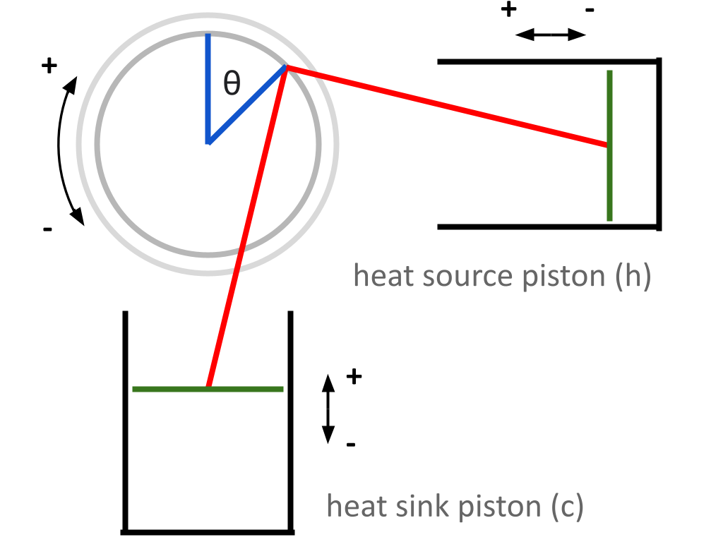
Here’s our coordinate system again, for reference.
We’ve already taken a look at the forces felt by the flywheel as a function of its angle \(\theta\). We found that the two forces experienced by the flywheel are: $$F_c = -F_p · cos \alpha_c · sin \beta_c · {|sin \theta| \over sin \theta}$$ $$F_h = -F_p · cos \alpha_h · sin \beta_h · {|cos \theta| \over cos \theta}$$
\(F_c\) and \(F_h\) represent the forces the flywheel feels as a result of the heat sink piston’s motion and the heat source piston’s motion, respectively. A derivation of these equations can be found in Entry 6. These forces are dependent on a number of other factors that have been conveniently wrapped up into \(F_p\) — which is the force felt by the piston heads as a result of the relative pressure difference between the interior and exterior of the piston cylinder. This force also varies indirectly based on \(\theta\). A thorough explanation of this relationship can be found in Entry 7.
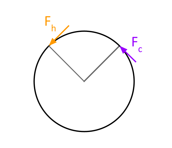
The forces \(F_c\) and \(F_p\) each represent the component of the force applied by their respective piston rods that is perpendicular to the flywheel’s radius — this is the component that contributes to the flywheel’s motion.
Shifting into the language of rotational dynamics, we will need to describe these forces as torques. Torque is simply the cross product of linear force and the radius at which the force is applied. Since \(F_c\) and \(F_h\) are already perpendicular to the flywheel’s radius, finding the magnitude of the applied torque simplifies to basic multiplication.
Recall that \(f\) represents that radius of the flywheel, as defined in Entry 6.
Let \(\tau_c\) represent the torque applied to the flywheel as a result of the heat sink piston’s motion (Nm)
Let \(\tau_h\) represent the torque applied to the flywheel as a result of the heat source piston’s motion (Nm) $$\tau_c = F_c × f$$ $$\tau_h = F_h × f$$
Now, we can also define the net torque on the flywheel.
Let \(\tau_{net}\) represent the net torque applied to the flywheel (Nm) $$\tau_{net} = \tau_c + \tau_h$$
\(\tau_{net}\) is the combined result of everything we’ve done so far — at any moment, it represents the overall torque applied to the flywheel, and changes solely with respect to \(\theta\) (although it does also depend on a number of other physical constants).
Our next step will be to look at the work done by this torque. Since the flywheel is a rotating body, calculating work will look a little different from how it usually looks in a linear setting.
(Full disclosure: I got the idea to calculate rotational work in this way from this site)
We already know that the work done by a constant force can, in general, be represented as: $$W = f · \Delta d$$
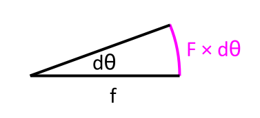
In the engine’s flywheel, however, the applied forces are not always constant. We can circumvent this issue for the moment by focusing on small rotations of the flywheel through an infinitesimally small \(d\theta\). In this span, the force applied is constant. The net force in the direction of motion pushes the flywheel through a distance of \(f × d\theta\).
Therefore, the infinitesimally small amount of work done in this interval is: $$\Delta d = f × d\theta$$
We can now solve for work.
Let \(W\) represent work done on the flywheel (J) $$dW = F_{net} · (f × d\theta)$$
We can rearrange this equation with the knowledge that \(a · (b × c) = b · (a × c)\). For a general intuition of this fact, it is helpful to think of \(a · (b × c)\) and \(b · (a × c)\) both representing the volume of the same parallelepiped. Rearranging, we get: $$dW = (F_{net} × f) · d\theta$$
Keeping in mind that net torque is the cross product of a net force and the radius at which it is applied, and remembering that in this engine, \(\tau_{net}\) represents the net torque on the flywheel at any point: $$dW = \tau_{net} · d\theta$$
It appears that net torque is the derivative of work: $${d \over d\theta} W = \tau_{net}$$
We can plot this on Desmos to see how the instantaneous work done on the engine varies with respect to \(\theta\).
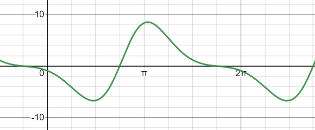
The observation I made in the last post still seems to hold — visually, there appears to be more positive work done on the flywheel than negative. This isn’t mathematically rigorous yet, though.
We know that \(\tau_{net}\) changes with respect to \(\theta\), so if we want to know the total amount of work done on the flywheel after it makes a rotation of \(\theta\), we can integrate τf over the interval 0 to \(\theta\). $$W = \int_{0}^{\theta} \tau_{net} \space d\theta + C$$
No work has been done initially when the flywheel has not yet rotated, so the value of C is 0. $$W = \int_{0}^{\theta} \tau_{net} \space d\theta$$
To be completely honest, I don’t have the background in calculus necessary to compute an integral of this complexity (at a glance this looks simple, but τnet actually has a ton of complexity wrapped up inside it). I’m going to let Desmos take care of computing that integral instead (judging by the time it takes to load the function, it seems complex even for a computer).
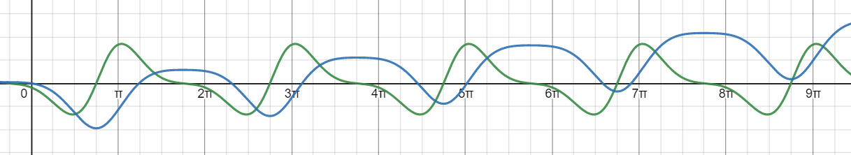
The blue line here represents the total work done on the flywheel with respect to \(\theta\). As the engine operates, the net amount of work done trends upwards, showing that more energy is produced by the engine than is consumed to keep it running. This is really exciting! This mathematical model, which considers the engine’s internal pressures, temperatures, and geometries, shows exactly what we expect — that a Stirling engine truly can do useful work! All of the physical parameters discussed in previous posts can now be tuned within this theoretical model to see how the engine’s performance is impacted.
Notice that initially, during the first couple of rotations, there are intervals where a net negative amount of work is done on the flywheel. This signifies that the expansion/contraction cycle of the pistons has consumed more energy from the flywheel than has been generated. The flywheel must contain a positive amount of energy at all times (otherwise the engine will stop), so it should start off with some initial amount of energy to ensure that even when a little negative work is done on it, it will still have some energy remaining. The net work done by the engine does trend upwards, so if there is a sufficient amount of initial energy within the flywheel to get past the intervals in the first few cycles where negative work is done, the engine then will be self sustaining (as long as an external temperature difference exists, of course). In layman’s terms, the engine needs a kickstart to start running!
We know that in general, work refers to a change in energy: $$W = \Delta E$$
So, the total amount of energy in the flywheel with respect to θ is:
Let \(E\) represent the total amount of energy in the flywheel (J)
Let \(E_{initial}\) represent the total amount of energy in the flywheel (J) $$E = E_{initial} + W$$
The flywheel stores energy in a rotational kinetic form, so I will be able to give it a kickstart by spinning it manually for a bit. We can assume that \(E_{initial}\) provides a sufficient kickstart. One question remains — how fast will the flywheel need to be spun initially to provide a sufficient kickstart? We need to make sure that this initial kickstart is at a reasonable speed, on a flywheel with a reasonable weight, so that the kickstart can be done manually.
I found a derivation online for how the rotational kinetic energy of a rotating body is calculated:
https://www.youtube.com/watch?v=PXWjKyg8krA
This equation can be used to calculate the initial velocity the flywheel must be spun at to give the engine a sufficient kickstart.
Let \(I\) represent the moment of inertia of the flywheel (kg m2)
Let \(\omega_{initial}\) represent the flywheel’s initial angular velocity (rad/s) $$E_{initial} = I {\omega_{initial}}^2$$ $$\omega_{initial} = \sqrt{E_{initial} \over I}$$
The flywheel’s moment of inertia depends on its mass distribution, and since computing it appears to require more advanced mathematical techniques than I am familiar with, I will probably just use an online calculator to find my flywheel’s moment of inertia. Once physical parameters are selected, I will be able to calculate the angular velocity required to kickstart the flywheel and ensure that it seems reasonable.
To sum it all up — right now, we have a theoretical model of a Stirling engine, where the relationship between different geometric features of the engine, the internal pressure and temperature, and the work done by the engine are all tied together. By adjusting physical parameters, it will be possible to see how certain design choices will impact the energy output of the engine.
All that remains is to actually design and construct the engine!
The Desmos graph used in this post can be found here:
https://www.desmos.com/calculator/o44oq3fzup
Here’s our coordinate system again, for reference.
We’ve already taken a look at the forces felt by the flywheel as a function of its angle \(\theta\). We found that the two forces experienced by the flywheel are: $$F_c = -F_p · cos \alpha_c · sin \beta_c · {|sin \theta| \over sin \theta}$$ $$F_h = -F_p · cos \alpha_h · sin \beta_h · {|cos \theta| \over cos \theta}$$
\(F_c\) and \(F_h\) represent the forces the flywheel feels as a result of the heat sink piston’s motion and the heat source piston’s motion, respectively. A derivation of these equations can be found in Entry 6. These forces are dependent on a number of other factors that have been conveniently wrapped up into \(F_p\) — which is the force felt by the piston heads as a result of the relative pressure difference between the interior and exterior of the piston cylinder. This force also varies indirectly based on \(\theta\). A thorough explanation of this relationship can be found in Entry 7.
The forces \(F_c\) and \(F_p\) each represent the component of the force applied by their respective piston rods that is perpendicular to the flywheel’s radius — this is the component that contributes to the flywheel’s motion.
Shifting into the language of rotational dynamics, we will need to describe these forces as torques. Torque is simply the cross product of linear force and the radius at which the force is applied. Since \(F_c\) and \(F_h\) are already perpendicular to the flywheel’s radius, finding the magnitude of the applied torque simplifies to basic multiplication.
Recall that \(f\) represents that radius of the flywheel, as defined in Entry 6.
Let \(\tau_c\) represent the torque applied to the flywheel as a result of the heat sink piston’s motion (Nm)
Let \(\tau_h\) represent the torque applied to the flywheel as a result of the heat source piston’s motion (Nm) $$\tau_c = F_c × f$$ $$\tau_h = F_h × f$$
Now, we can also define the net torque on the flywheel.
Let \(\tau_{net}\) represent the net torque applied to the flywheel (Nm) $$\tau_{net} = \tau_c + \tau_h$$
\(\tau_{net}\) is the combined result of everything we’ve done so far — at any moment, it represents the overall torque applied to the flywheel, and changes solely with respect to \(\theta\) (although it does also depend on a number of other physical constants).
Our next step will be to look at the work done by this torque. Since the flywheel is a rotating body, calculating work will look a little different from how it usually looks in a linear setting.
(Full disclosure: I got the idea to calculate rotational work in this way from this site)
We already know that the work done by a constant force can, in general, be represented as: $$W = f · \Delta d$$
In the engine’s flywheel, however, the applied forces are not always constant. We can circumvent this issue for the moment by focusing on small rotations of the flywheel through an infinitesimally small \(d\theta\). In this span, the force applied is constant. The net force in the direction of motion pushes the flywheel through a distance of \(f × d\theta\).
Therefore, the infinitesimally small amount of work done in this interval is: $$\Delta d = f × d\theta$$
We can now solve for work.
Let \(W\) represent work done on the flywheel (J) $$dW = F_{net} · (f × d\theta)$$
We can rearrange this equation with the knowledge that \(a · (b × c) = b · (a × c)\). For a general intuition of this fact, it is helpful to think of \(a · (b × c)\) and \(b · (a × c)\) both representing the volume of the same parallelepiped. Rearranging, we get: $$dW = (F_{net} × f) · d\theta$$
Keeping in mind that net torque is the cross product of a net force and the radius at which it is applied, and remembering that in this engine, \(\tau_{net}\) represents the net torque on the flywheel at any point: $$dW = \tau_{net} · d\theta$$
It appears that net torque is the derivative of work: $${d \over d\theta} W = \tau_{net}$$
We can plot this on Desmos to see how the instantaneous work done on the engine varies with respect to \(\theta\).
The observation I made in the last post still seems to hold — visually, there appears to be more positive work done on the flywheel than negative. This isn’t mathematically rigorous yet, though.
We know that \(\tau_{net}\) changes with respect to \(\theta\), so if we want to know the total amount of work done on the flywheel after it makes a rotation of \(\theta\), we can integrate τf over the interval 0 to \(\theta\). $$W = \int_{0}^{\theta} \tau_{net} \space d\theta + C$$
No work has been done initially when the flywheel has not yet rotated, so the value of C is 0. $$W = \int_{0}^{\theta} \tau_{net} \space d\theta$$
To be completely honest, I don’t have the background in calculus necessary to compute an integral of this complexity (at a glance this looks simple, but τnet actually has a ton of complexity wrapped up inside it). I’m going to let Desmos take care of computing that integral instead (judging by the time it takes to load the function, it seems complex even for a computer).
The blue line here represents the total work done on the flywheel with respect to \(\theta\). As the engine operates, the net amount of work done trends upwards, showing that more energy is produced by the engine than is consumed to keep it running. This is really exciting! This mathematical model, which considers the engine’s internal pressures, temperatures, and geometries, shows exactly what we expect — that a Stirling engine truly can do useful work! All of the physical parameters discussed in previous posts can now be tuned within this theoretical model to see how the engine’s performance is impacted.
Notice that initially, during the first couple of rotations, there are intervals where a net negative amount of work is done on the flywheel. This signifies that the expansion/contraction cycle of the pistons has consumed more energy from the flywheel than has been generated. The flywheel must contain a positive amount of energy at all times (otherwise the engine will stop), so it should start off with some initial amount of energy to ensure that even when a little negative work is done on it, it will still have some energy remaining. The net work done by the engine does trend upwards, so if there is a sufficient amount of initial energy within the flywheel to get past the intervals in the first few cycles where negative work is done, the engine then will be self sustaining (as long as an external temperature difference exists, of course). In layman’s terms, the engine needs a kickstart to start running!
We know that in general, work refers to a change in energy: $$W = \Delta E$$
So, the total amount of energy in the flywheel with respect to θ is:
Let \(E\) represent the total amount of energy in the flywheel (J)
Let \(E_{initial}\) represent the total amount of energy in the flywheel (J) $$E = E_{initial} + W$$
The flywheel stores energy in a rotational kinetic form, so I will be able to give it a kickstart by spinning it manually for a bit. We can assume that \(E_{initial}\) provides a sufficient kickstart. One question remains — how fast will the flywheel need to be spun initially to provide a sufficient kickstart? We need to make sure that this initial kickstart is at a reasonable speed, on a flywheel with a reasonable weight, so that the kickstart can be done manually.
I found a derivation online for how the rotational kinetic energy of a rotating body is calculated:
https://www.youtube.com/watch?v=PXWjKyg8krA
This equation can be used to calculate the initial velocity the flywheel must be spun at to give the engine a sufficient kickstart.
Let \(I\) represent the moment of inertia of the flywheel (kg m2)
Let \(\omega_{initial}\) represent the flywheel’s initial angular velocity (rad/s) $$E_{initial} = I {\omega_{initial}}^2$$ $$\omega_{initial} = \sqrt{E_{initial} \over I}$$
The flywheel’s moment of inertia depends on its mass distribution, and since computing it appears to require more advanced mathematical techniques than I am familiar with, I will probably just use an online calculator to find my flywheel’s moment of inertia. Once physical parameters are selected, I will be able to calculate the angular velocity required to kickstart the flywheel and ensure that it seems reasonable.
To sum it all up — right now, we have a theoretical model of a Stirling engine, where the relationship between different geometric features of the engine, the internal pressure and temperature, and the work done by the engine are all tied together. By adjusting physical parameters, it will be possible to see how certain design choices will impact the energy output of the engine.
All that remains is to actually design and construct the engine!
The Desmos graph used in this post can be found here:
https://www.desmos.com/calculator/o44oq3fzup