Engine Design
Now that we have a working mathematical model of the engine, we can take a closer look at how certain design choices impact the performance of the engine.
First, a recap of the physical parameters we have control over.
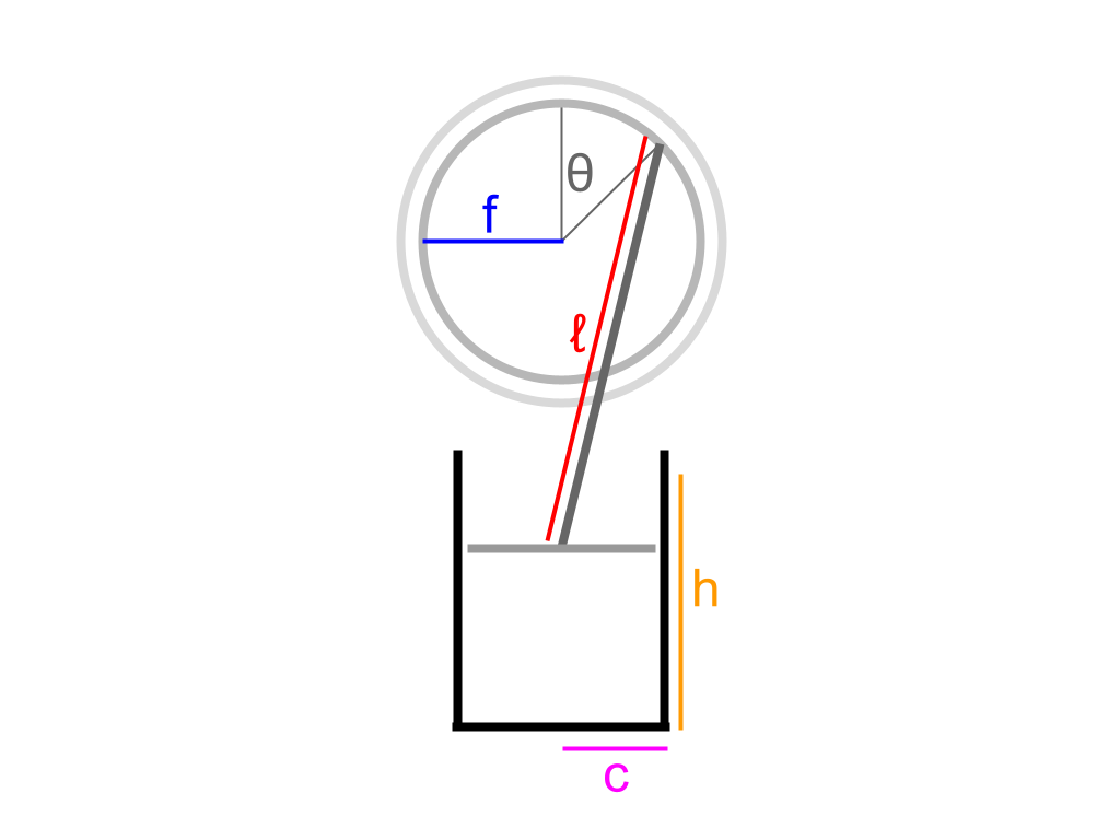
\(ℓ\) represents the length of the piston rod (m)
\(f\) represents the radius of the flywheel (m)
\(h\) represents the length of the piston cylinders (m)
\(c\) represents the radius of the piston cylinders (m)
\(T_c\) represents the internal temperature of the heat sink cylinder (K)
\(T_h\) represents the internal temperature of the heat source cylinder (K)
I also made the assumption in a previous post that I can fit 1.75 piston cylinders worth of air into the engine. The more air I can fit into the cylinders, the more work the engine can do, according to the theoretical model. The maximum amount of air I can fit in is 2 cylinders worth, and I doubt I will be able to fit all of the air in perfectly, so 1.75 cylinders worth of air seems like a reasonable assumption that I’ll stick with.
This leaves us with 6 parameters to play with. \(W\) (which represents total work done) is a function of \(\theta\), and contains these 6 parameters. See the last 3 posts for a thorough explanation of how these variables relate to \(W\). Our goal is to maximize W after a finite rotation of \(\theta\).
\(T_c\) is the internal temperature of the heat sink cylinder. In this engine, the heat sink will be the surrounding atmosphere, so we can assume that the internal temperature of the cylinder will be room temperature. This is 293 K.
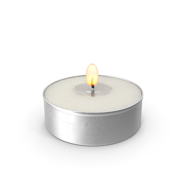
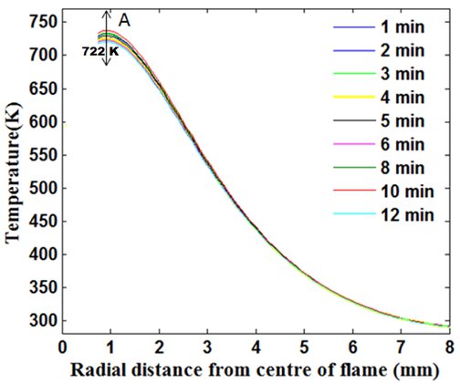
\(T_h\) is the internal temperature of the heat source cylinder. In this engine, the heat source will be a small tea candle placed right below the cylinder. To find a reasonable temperature for the cylinder, I did a little research. I found a paper that outlines the relationship between a candle’s temperature and the distance from the flame. I should be able to get the cylinder to a temperature of 370 K (97o C) if it is 5 mm from the center of the flame, assuming that the cylinder is a good enough conductor of heat that it can somewhat evenly heat its own interior. It might take a little while to heat the interior of the cylinder up to this temperature, though.
 There are 4 remaining geometric parameters that need to be tuned: \(ℓ\), \(f\), \(h\), and \(c\). There are a couple of relative constraints between them:
$$ℓ > 2f$$
$$h > 2f$$
There are 4 remaining geometric parameters that need to be tuned: \(ℓ\), \(f\), \(h\), and \(c\). There are a couple of relative constraints between them:
$$ℓ > 2f$$
$$h > 2f$$
This should be apparent when looking at the diagram of the piston and the flywheel.
According to the theoretical model, the larger \(ℓ\), \(f\), and \(c\) are, the greater the power output of the engine. It is worth noting that after increasing \(ℓ\) enough, there are diminishing returns to the engine’s power output, so it becomes less important to maximize \(ℓ\) after a point. Meanwhile, the smaller \(h\) is, the greater the power output of the engine.
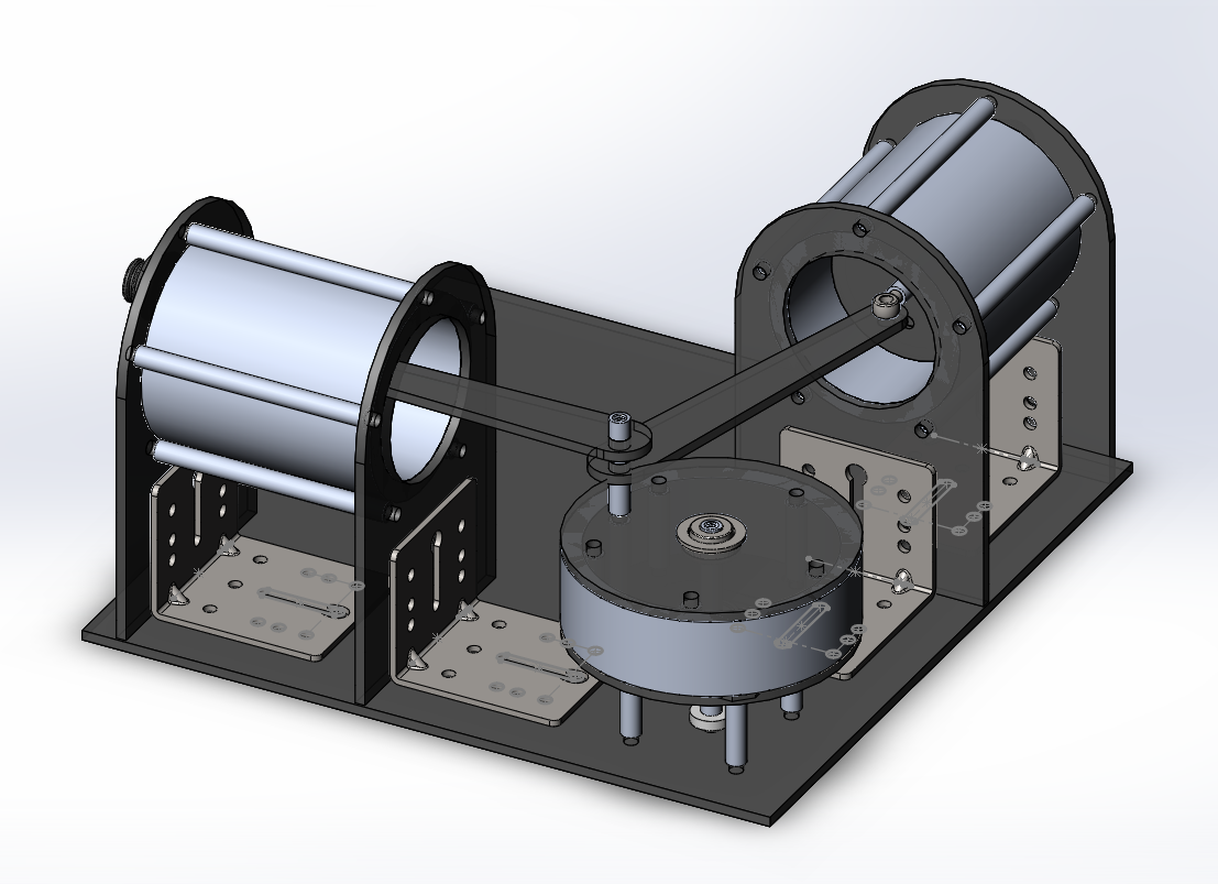
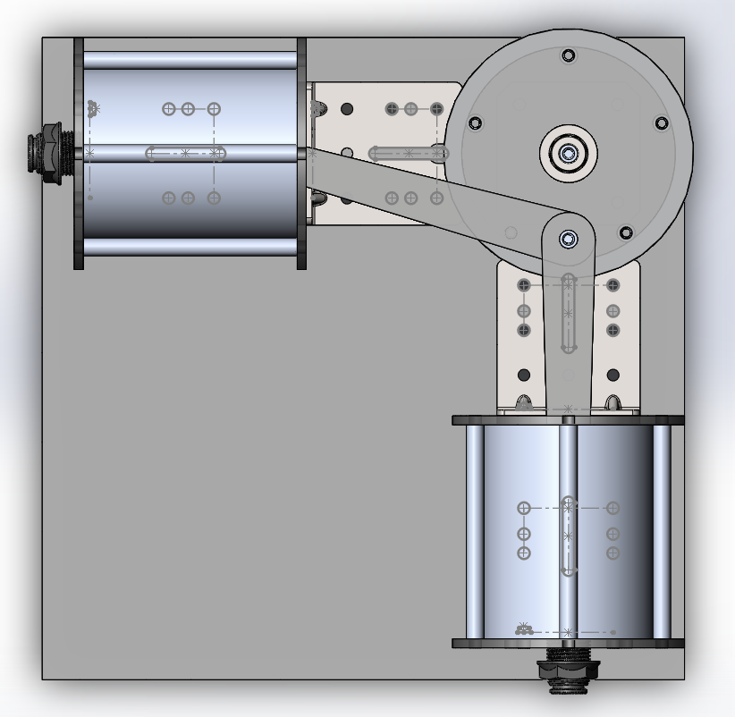
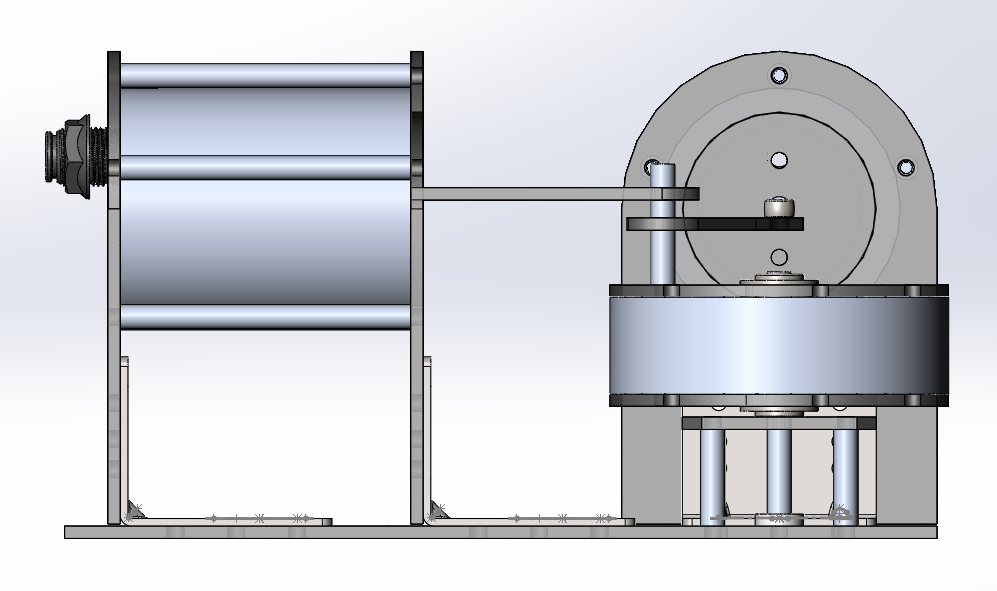
Aside from the theory, though, there are limits to the size of the engine’s components, since larger components will be more difficult to work with, and more expensive. For this reason, I’ve decided to design the engine first without worrying about these constraints, then to tune them to maximize efficiency given the general design I’ve laid out. I’ve gone ahead and designed the entire engine using CAD software — I’m using Solidworks for this. I’m not covering this process in detail since it didn’t really involve very much physics.

After numerous hours designing the engine so that it could actually be constructed in real life, I settled on my parameters, guided by my theoretical model. These have been chosen in Imperial units since most industrial parts, even here in Canada, use Imperial standards. I’ll convert back to metric to plug these parameters into the theoretical model.
I used the theoretical model to inform some of my parameter choices. I chose to make \(c=1''\), since that seemed like a reasonable size for a piston cylinder. This is a fairly standard cylinder size, which made it easier to find a seal for the piston head. I also chose to make \(f=1.5''\) initially, since I didn’t want the flywheel to take up too much space. I then made \(h=3''\), since \(h\) must be at least double \(f\), and because it must be minimized in order to maximize the engine’s power output. This is a good, standard cylinder length, but I realized that some space at the end of the cylinder would be taken up by other hardware, and so \(f\) had to be reduced down to \(f=1.2''\) so that the piston’s inward stroke wouldn’t extend into this space. I finally set \(ℓ=4.5''\), since that seemed like a reasonable length, and because any further increase in the piston rod length would make the engine sprawl out even more. It isn’t worth increasing \(ℓ\) by too much more, since increasing it has diminishing returns on the engine’s power output, according to the theoretical model.
This is the work output of the engine with these parameters, as a function of θ:
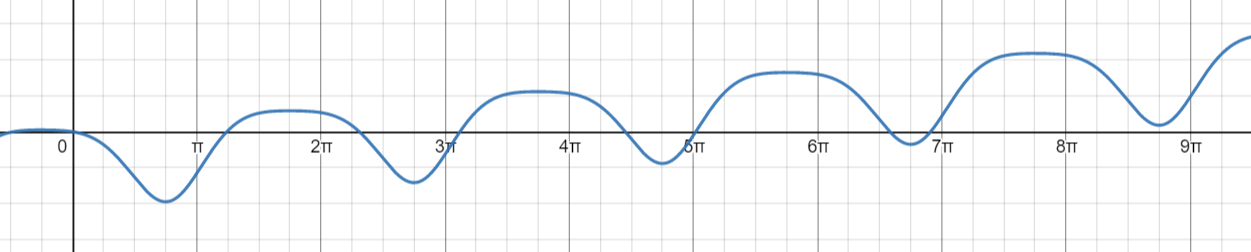
This Desmos graph can be found here: https://www.desmos.com/calculator/gakv9ysnx3
I also want to briefly touch on the mechanical design of this engine. All custom components are to be made out of Lexan (the type of plastic I mentioned in a previous post). I will cut these pieces myself on my mini CNC router. All of the other parts in this engine are from McMaster-Carr, the industrial hardware shop I mentioned in earlier posts, and from a local metal store called Metal Supermarkets.
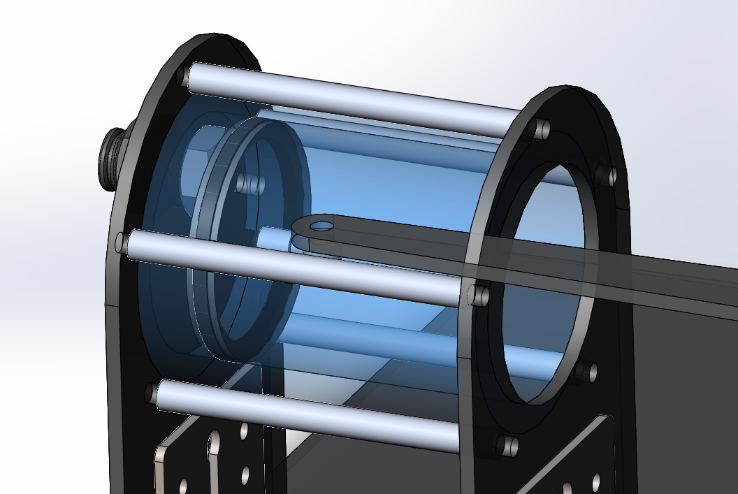
(I will be referring to standoffs when describing the engine — standoffs are thin, threaded metal rods, and can be identified in the images of the CAD model above)
Three steel round tubes are from Metal Supermarkets — these make up the two piston cylinder walls, and the flywheel mass. The tube that is the flywheel mass has a wider diameter than the two piston cylinder tubes. Initially, I wanted to order aluminum equivalents of these tubes from McMaster-Carr, but there were exorbitantly high duties on them since they’re coming from the US, and so I settled for these steel tubes instead. Although steel may be harder to support due to its higher density and extra weight, a steel mass will give the flywheel a much higher moment of inertia, which could be a good thing. Each of these steel tubes are held in place between two sheets of Lexan, and they each have a few standoffs tangent to their surface that secure them in place to prevent movement, while also clamping their ends to the Lexan sheets.
The flywheel’s mass is distributed close to its edge to maximize its rotational inertia. The flywheel also contains two bearings, which allow it to rotate on a fixed standoff. This standoff passes through a supporting plate made of Lexan to help keep it stable.
The piston heads contain an airtight sealing ring which is sandwiched between pieces of Lexan. Each piston head has an eye bolt running through it that connects the piston head to a piston rod. On the other end, each piston rod is attached to a single standoff on the flywheel located a distance \(f\) from the center of the flywheel.
A bulkhead pipe fitting passes through the Lexan backside of each piston — a plastic tube will be connected between these fittings, allowing air to pass between the cylinders freely and without any leaks.
Through the power of delayed blog writing, I’ve already ordered these parts, and after some online purchasing shenanigans that are irrelevant to this post, I’m happy to say that I now have everything I need. All that’s left now is to actually construct the engine!
First, a recap of the physical parameters we have control over.
\(ℓ\) represents the length of the piston rod (m)
\(f\) represents the radius of the flywheel (m)
\(h\) represents the length of the piston cylinders (m)
\(c\) represents the radius of the piston cylinders (m)
\(T_c\) represents the internal temperature of the heat sink cylinder (K)
\(T_h\) represents the internal temperature of the heat source cylinder (K)
I also made the assumption in a previous post that I can fit 1.75 piston cylinders worth of air into the engine. The more air I can fit into the cylinders, the more work the engine can do, according to the theoretical model. The maximum amount of air I can fit in is 2 cylinders worth, and I doubt I will be able to fit all of the air in perfectly, so 1.75 cylinders worth of air seems like a reasonable assumption that I’ll stick with.
This leaves us with 6 parameters to play with. \(W\) (which represents total work done) is a function of \(\theta\), and contains these 6 parameters. See the last 3 posts for a thorough explanation of how these variables relate to \(W\). Our goal is to maximize W after a finite rotation of \(\theta\).
\(T_c\) is the internal temperature of the heat sink cylinder. In this engine, the heat sink will be the surrounding atmosphere, so we can assume that the internal temperature of the cylinder will be room temperature. This is 293 K.
\(T_h\) is the internal temperature of the heat source cylinder. In this engine, the heat source will be a small tea candle placed right below the cylinder. To find a reasonable temperature for the cylinder, I did a little research. I found a paper that outlines the relationship between a candle’s temperature and the distance from the flame. I should be able to get the cylinder to a temperature of 370 K (97o C) if it is 5 mm from the center of the flame, assuming that the cylinder is a good enough conductor of heat that it can somewhat evenly heat its own interior. It might take a little while to heat the interior of the cylinder up to this temperature, though.
This should be apparent when looking at the diagram of the piston and the flywheel.
According to the theoretical model, the larger \(ℓ\), \(f\), and \(c\) are, the greater the power output of the engine. It is worth noting that after increasing \(ℓ\) enough, there are diminishing returns to the engine’s power output, so it becomes less important to maximize \(ℓ\) after a point. Meanwhile, the smaller \(h\) is, the greater the power output of the engine.
Aside from the theory, though, there are limits to the size of the engine’s components, since larger components will be more difficult to work with, and more expensive. For this reason, I’ve decided to design the engine first without worrying about these constraints, then to tune them to maximize efficiency given the general design I’ve laid out. I’ve gone ahead and designed the entire engine using CAD software — I’m using Solidworks for this. I’m not covering this process in detail since it didn’t really involve very much physics.
After numerous hours designing the engine so that it could actually be constructed in real life, I settled on my parameters, guided by my theoretical model. These have been chosen in Imperial units since most industrial parts, even here in Canada, use Imperial standards. I’ll convert back to metric to plug these parameters into the theoretical model.
I used the theoretical model to inform some of my parameter choices. I chose to make \(c=1''\), since that seemed like a reasonable size for a piston cylinder. This is a fairly standard cylinder size, which made it easier to find a seal for the piston head. I also chose to make \(f=1.5''\) initially, since I didn’t want the flywheel to take up too much space. I then made \(h=3''\), since \(h\) must be at least double \(f\), and because it must be minimized in order to maximize the engine’s power output. This is a good, standard cylinder length, but I realized that some space at the end of the cylinder would be taken up by other hardware, and so \(f\) had to be reduced down to \(f=1.2''\) so that the piston’s inward stroke wouldn’t extend into this space. I finally set \(ℓ=4.5''\), since that seemed like a reasonable length, and because any further increase in the piston rod length would make the engine sprawl out even more. It isn’t worth increasing \(ℓ\) by too much more, since increasing it has diminishing returns on the engine’s power output, according to the theoretical model.
This is the work output of the engine with these parameters, as a function of θ:
This Desmos graph can be found here: https://www.desmos.com/calculator/gakv9ysnx3
I also want to briefly touch on the mechanical design of this engine. All custom components are to be made out of Lexan (the type of plastic I mentioned in a previous post). I will cut these pieces myself on my mini CNC router. All of the other parts in this engine are from McMaster-Carr, the industrial hardware shop I mentioned in earlier posts, and from a local metal store called Metal Supermarkets.
(I will be referring to standoffs when describing the engine — standoffs are thin, threaded metal rods, and can be identified in the images of the CAD model above)
Three steel round tubes are from Metal Supermarkets — these make up the two piston cylinder walls, and the flywheel mass. The tube that is the flywheel mass has a wider diameter than the two piston cylinder tubes. Initially, I wanted to order aluminum equivalents of these tubes from McMaster-Carr, but there were exorbitantly high duties on them since they’re coming from the US, and so I settled for these steel tubes instead. Although steel may be harder to support due to its higher density and extra weight, a steel mass will give the flywheel a much higher moment of inertia, which could be a good thing. Each of these steel tubes are held in place between two sheets of Lexan, and they each have a few standoffs tangent to their surface that secure them in place to prevent movement, while also clamping their ends to the Lexan sheets.
The flywheel’s mass is distributed close to its edge to maximize its rotational inertia. The flywheel also contains two bearings, which allow it to rotate on a fixed standoff. This standoff passes through a supporting plate made of Lexan to help keep it stable.
The piston heads contain an airtight sealing ring which is sandwiched between pieces of Lexan. Each piston head has an eye bolt running through it that connects the piston head to a piston rod. On the other end, each piston rod is attached to a single standoff on the flywheel located a distance \(f\) from the center of the flywheel.
A bulkhead pipe fitting passes through the Lexan backside of each piston — a plastic tube will be connected between these fittings, allowing air to pass between the cylinders freely and without any leaks.
Through the power of delayed blog writing, I’ve already ordered these parts, and after some online purchasing shenanigans that are irrelevant to this post, I’m happy to say that I now have everything I need. All that’s left now is to actually construct the engine!